Badge Assembly
Look the board over and locate the listed part numbers. Note any items that have a specific orientation or polarization.
If you have never soldered before review the guide below for instructions.
Where do I start
The following items are in your conference bag:
- Badge PCB.
- Bag of resistors, capacitors, fuses, headers,
- D1 Mini ESP8266 development board.
- Bag containing 2x male headers, 2x female headers, and 2x stacking headers.
- USB battery
- Screw or washer to exchange for the following at HHV:
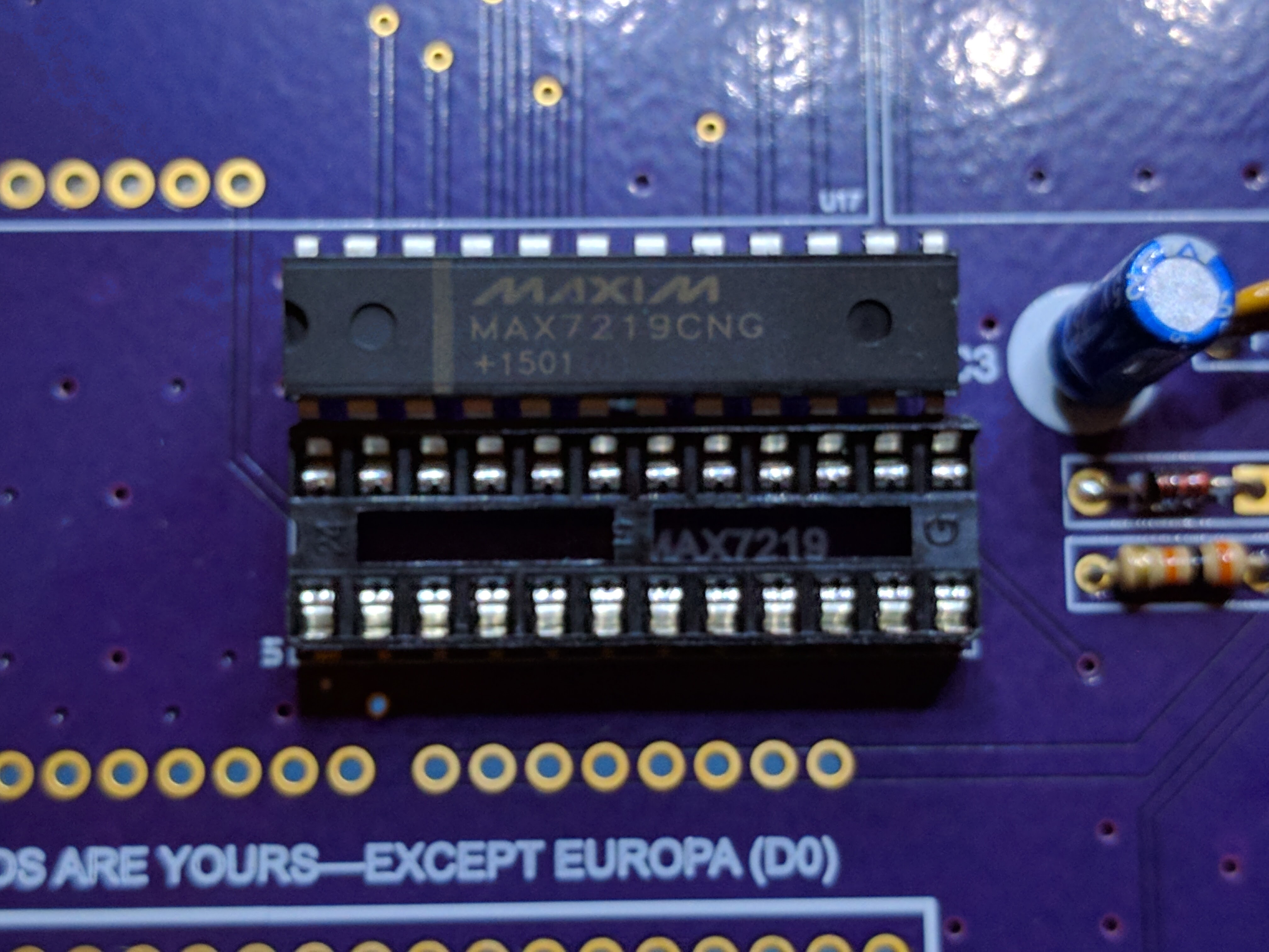
- MAX7219 LED driver IC.
- 2x 4 digit LEDs (yellow, green, red, white, and eye searing blue).
- See photos below
Assembly gotchas
- Don't directly solder the D1 Mini or the MAX 7219 chip to the board. Solder the included headers and IC socket in place first.
- Solder small items like diodes and resistors first.
- Solder one pin on the IC socket or header, then heat that pin up while using a free hand to straighten the part. Don't touch any hot parts!!
- Place female pins on the board and male or stacking headers on the D1 mini. Check orientation first!
- When attaching the D1 mini to the board the FCC logo should be face up. See side view and pins/socket.
- Which side of the diode is positive? https://learn.sparkfun.com/tutorials/polarity/diode-and-led-polarity
- Solder LEDs directly to the badge. Use of headers will lead to loose connections.
Bill of Materials
| Qty | Board Label | Description |
|---|---|---|
| 1 | C1 | 0.1uf Ceramic Capacitor |
| 1 | C3 | 10uf Electrolytic Capacitor polarized |
| 1 | D1 | 1N4148 Signal Diode polarized |
| 1 | iset | Resistor which resistor? |
| 2 | F5 F6 | 500ma PolySwitch PTC Fuse |
| 1 | U1 | 24 pin IC Socket polarized |
| 1 | U1 | MAX 7219 LED Driver polarized |
| 2 | U16 U17 | 4 digit 7-segment LED display polarized |
| 1 | U58 | Wemos D1 Mini + included headers polarized |
| 5 | various | 8x1 Female headers |
Resistor selection
The iset resistor is used to limit the current draw of the LEDs. The resistor must be chosen with the LED forward voltage and forward current in mind. Use the table below to select which of the two resistors you need to use on your badge. There are limited quantities of the various colors. Don't solder the resistor until you have your LEDs in hand!
| LED Color | iset resistor value |
|---|---|
| Green | 18k ohm |
| White | 30k ohm |
| Blue | 30k ohm |
| Yellow | 30k ohm |
| Red | 30k ohm |
Resistor Color Code Calculator
Schematic
![]()
Finished examples

![]()
![]()
![]()